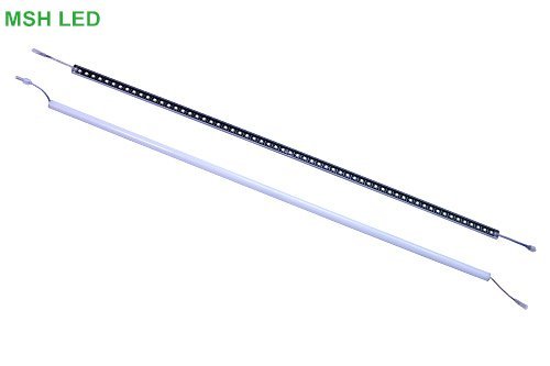
Description
LED Lights with SK6812 Addressable led strips
Overview: which uses SK6812 driver IC and 5050RGB lamp beads to achieve the purpose of DC5V drive and 3 lamps and 1 control,
reducing the impact of voltage drop. The only power is required at both ends every 5 meters. The light bar panel looks very simple
and beautiful, and it is also a very stable driver with very high brightness. The lamp beads made with it have high brightness,
stable performance, simple surface, beautiful appearance, convenient production, low cost, and low failure rate …
It is an ideal design choice for lighting bright outdoor lighting.
Product Parameter
| PN | B017060-SK6812RGB |
| Voltage | DC5V |
| LED Type | SMD 5050RGB |
| LED Quantity | 60LEDs/pcs |
| Protocol | SPI-SK6812 |
| Dimension | 1000*17 MM |
| Emitting Color | Full color |
| PCB Color | Black |
| Power | 18W/M |
| O.T | -30℃ ~ 45℃ |
Description:
The board designed by 60pcs sk6812 RGB LED,
Each tube included 2pcs Aluminum clips(without screw) It’s cannot adjust the angle but it’s move-able horizontal
Each tube attached a pair of waterproof 3Pin connector output from the bottom side, this could achieve a no-slot joint.
Although it’s DC5V working, the addressable linear still requested to feed power every 5 meters
Protocol
These LED bars are controlled by a simple, high-speed one-wire protocol on the input signal line. The protocol is documented in the SK6812 datasheet (459k pdf) and also below.
The default, idle state of the signal line is low. To update the LED colors, you need to transmit a series of high pulses on the signal line. Each high pulse encodes one bit: a short pulse (0.35 μs) represents a zero, while a long pulse (0.9 μs) represents a one. The time between consecutive rising edges should be 1.25 μs (though in our tests, the strips worked with cycle times up to approximately 39 μs). After the bits are sent, the signal line should be held low for 80 μs to send a reset command, which makes the new color data take effect (note: it is possible for low pulses as short as 40 μs to trigger a reset). The pulse widths do not have to be precise: there is a threshold that determines whether the pulse is a 0 or a 1, and a wide range of pulse widths on both sides of the threshold will work.
The color of each LED is encoded as three LED brightness values, which must be sent in the GRB (green-red-blue) order. Each brightness value is encoded as a series of 8 bits, with the most significant bit being transmitted first, so each LED color takes 24 bits. The first color transmitted applies to the LED that is closest to the data input connector, while the second color transmitted applies to the next LED in the strip, and so on.


Reviews
There are no reviews yet.